
Hamilton Standard Propulsion Model#
In the 1970s, NASA contracted Hamilton Standard to forecast into the future mid-80s to the 90s what they thought advanced propellers would look like. The result is what we call “Hamilton Standard model” used in Aviary today. The Hamilton Standard Documentation is publicly available. You can find the definitions, methodology, and Fortran code in the document. In Aviary, we implement only one of the computation options: the code computes the corresponding thrust for a given horsepower.
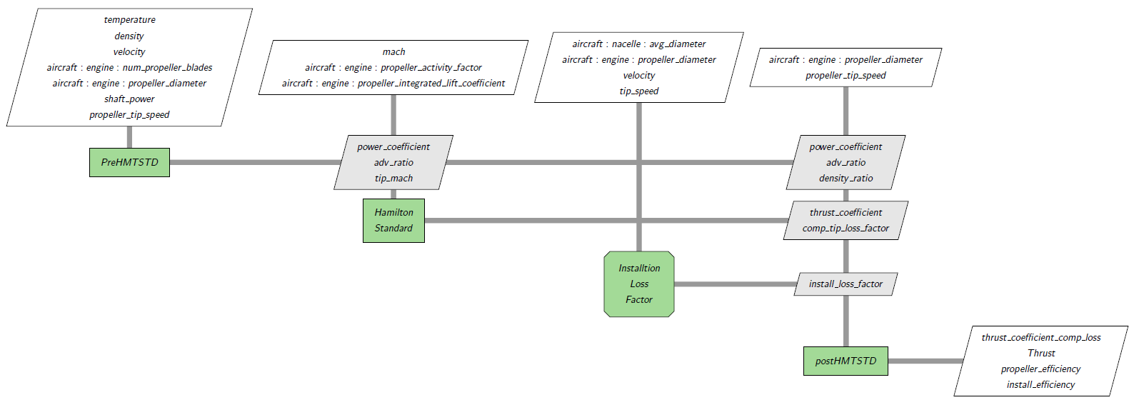
Below is an XDSM diagram of Hamilton Standard model (assuming Aircraft.Engine.Propeller.COMPUTE_INSTALLATION_LOSS is True):
The inputs are grouped in three aspects:
Geometric inputs:
Propeller diameter
Activity factor per blade (range: 80 to 200, baseline: 150)
Number of blades (range: 2 to 8)
Power inputs:
Shaft power to propeller (hp)
Installation loss factor (0 to 1)
Performance inputs:
Operating altitude (ft)
True airspeed (knots)
Propeller tip speed (Usually < 800 ft/s)
Integrated lift coefficient (range: 0.3 to 0.8, baseline: 0.5)
Some of the inputs are valid for limited ranges. When using an odd number of blades, the Hamilton Standard model interpolates using the 2, 4, 6 and 8 blade data. The corresponding outputs are:
Geometric outputs:
Design blade pitch angle (at 0.75 Radius)
Power outputs:
Installation loss factor
Tip compressibility loss factor
Power coefficient
Thrust coefficient (rho=const, no losses)
Performance outputs:
Flight Mach number
Propeller tip Mach number
Advance ratio
Tip compressibility loss factor
Thrust
Propeller efficiency with compressibility losses
Propeller efficiency with compressibility and installation losses
When shaft power is zero, propeller efficiencies are undefined. We set them as 0.0.
As shown in the above XDSM diagram, the model is an OpenMDAO group that is composed of three components and two groups:
Atmosphere(group)PreHamiltonStandardHamiltonStandardInstallLoss(group)PostHamiltonStandard
The Atmosphere component provides the flight conditions.
The flight conditions are passed to the PreHamiltonStandard component which computes the propeller tip Mach number, advance ratio, and power coefficient.
These values are then fed into the HamiltonStandard component.
HamiltonStandard is the core of the model.
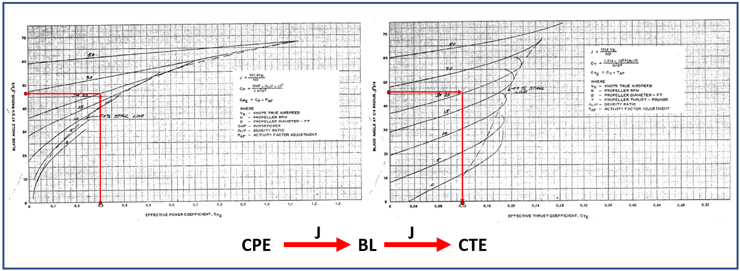
Given the power coefficient (CP) and advance ratio (J), it finds the blade angle (BL) by a CP-BL chart by tracing the advance ratio.
Then with the blade angle, it finds the thrust coefficient (CT) using its CT-BL chart by tracing advance ratio again.
This algorithm is shown in the below pair of charts.
The CP → BL → CT chart matching algorithm is based on baseline data.
If the user-inputted values are not in the valid region, it will first convert them to those baseline parameters by a sequence of interpolations to do the necessary corrections.
The newly converted parameters are called “effective parameters” (e.g., CPE and CTE).
The outputs are blade angle, thrust coefficient and tip compressibility loss factor.
Finally, the thrust is computed in the PostHamiltonStandard component based on thrust coefficient and tip compressibility loss factor.
The Hamilton Standard model uses wind tunnel test data from uninstalled propellers. When a nacelle is mounted behind the propeller, an installation loss factor is introduced. The installation loss factor can be given by the user or computed. If it is computed, we need another group of components as shown below:
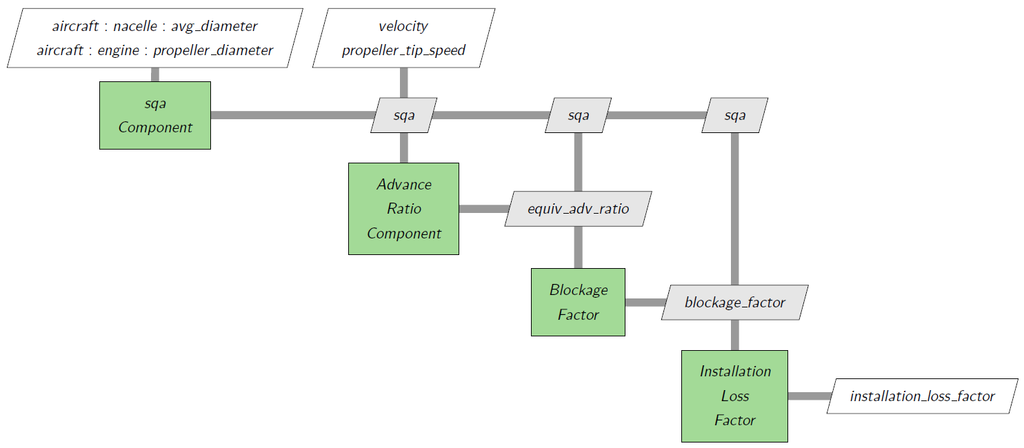
This diagram is represented by InstallLoss group in the first diagram.
Nacelle diameter is needed when installation loss factor is computed.
We use the average nacelle diameter.
The newly added aviary options and variables are:
Aircraft.Engine.Propeller.DIAMETER
Aircraft.Engine.Propeller.INTEGRATED_LIFT_COEFFICIENT
Aircraft.Engine.Propeller.ACTIVITY_FACTOR
Aircraft.Engine.Propeller.NUM_BLADES
Aircraft.Engine.Propeller.COMPUTE_INSTALLATION_LOSS
Dynamic.Vehicle.Propulsion.PROPELLER_TIP_SPEED
Dynamic.Vehicle.Propulsion.SHAFT_POWER
To build a turboprop engine that uses the Hamilton Standard propeller model we use a TurbopropModel object without providing a custom propeller_model, here it is set to None (the default). In this example, we also set shaft_power_model to None, another default that assumes we are using a turboshaft engine deck:
engine = TurbopropModel(options=options, shaft_power_model=None, propeller_model=None)
Some inputs are options:
options.set_val(Aircraft.Engine.Propeller.DIAMETER, 10, units='ft')
options.set_val(Aircraft.Engine.Propeller.NUM_BLADES, val=4, units='unitless')
options.set_val(Aircraft.Engine.Propeller.COMPUTE_INSTALLATION_LOSS, val=True, units='unitless')
We set the inputs like the following:
prob.set_val(f'traj.cruise.rhs_all.{Aircraft.Engine.Propeller.TIP_SPEED_MAX}', 710.0, units='ft/s')
prob.set_val(
    f'traj.cruise.rhs_all.{Aircraft.Engine.Propeller.ACTIVITY_FACTOR}', 150.0, units='unitless'
)
prob.set_val(
    f'traj.cruise.rhs_all.{Aircraft.Engine.Propeller.INTEGRATED_LIFT_COEFFICIENT}',
    0.5,
    units='unitless',
)
Propeller Map Alternative#
The Hamilton Standard model has limitations where it can be applied; for model aircraft design, it is possible that users may want to provide their own data tables. Two sample data sets are provided in models/engines/propellers folder: general_aviation.csv and PropFan.csv. In both cases, they are in .csv format and are converted from GASP maps: general_aviation.csv and PropFan.csv (see Command Line Tools for details). The difference between these two samples is that the general aviation sample uses helical Mach numbers as input while the propfan sample uses the free stream Mach numbers. Helical Mach numbers appear higher, due to the inclusion of the rotational component of the tip velocity. In our example, they range from 0.7 to 0.95. To determine which mach type in a GASP map is used, look at the first integer of the first line. If it is 1, it uses helical mach; if it is 2, it uses free stream mach. To determine which mach type is an Aviary propeller file is used, look at which variables are present in the header. It is typically either helical_mach or mach. If both are present in the header, Aviary will directly use the data in the Mach number column.
To use a propeller map, users can provide the propeller map file path to Aircraft.Engine.Propeller.DATA_FILE.
In the Hamilton Standard models, the thrust coefficients do not take compressibility into account. Therefore, propeller tip compressibility loss factor has to be computed and will be used to compute thrust. If a propeller map is used, the compressibility effects should be included in the data provided. Therefore, this factor is assumed to be 1.0 and is supplied to post Hamilton Standard component. Other outputs are computed using the same formulas.