
Electric Motor Modelling#
Aviary provides the capability to include electric motors as part of the propulsion system of the aircraft, including attaching one to a gearbox or propeller. In this section we will detail how the basic electric motor model included with Aviary works and point to a few examples of its implementation.
The electric motor model is for a fixed RPM motor.
The electric motor model is considered an External Subsystem.
As an external subsystem, Overrides attempting to set internal variables inside the model will not work.
The model has a builder MotorBuilder() and two components, a motor_premission() component and a motor_mission() component.
The MotorBuilder() contains the definitions of all of the inputs, outputs, and constraints required by the motor model.
It will also need a motor map .csv file that can be specified by the user through setting Aircraft.Engine.Motor.DATA_FILE with the file path string.
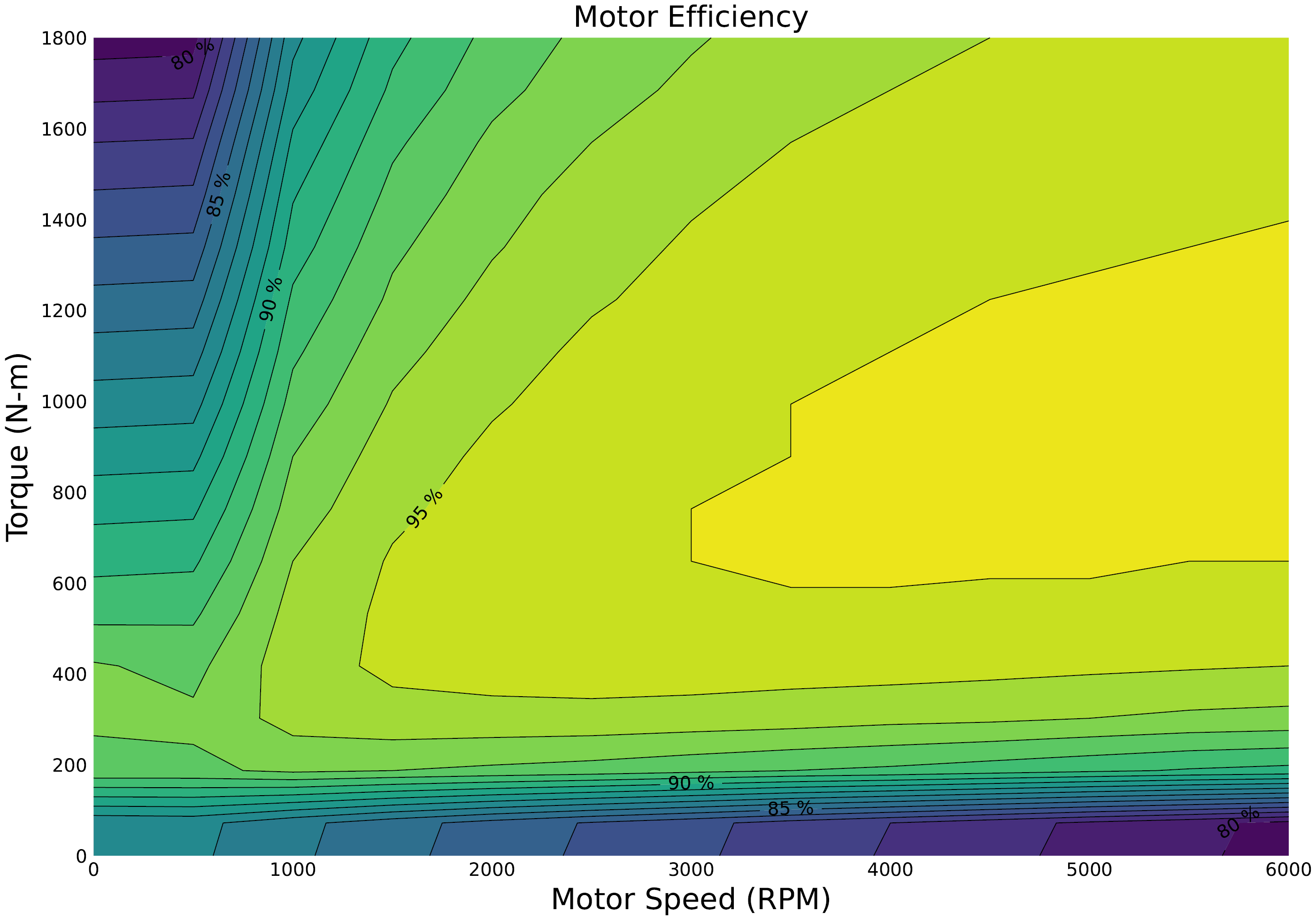
Users can supply their own motor map or use the example map provided by electric_motor_1800Nm_6000rpm.csv.
Motor Premission#
Motor premission has the primary purpose of determining electric motor weight before the mission is flown.
This weight is a function of scale factor and motor torque.
The Aircraft.Engine.SCALE_FACTOR scales the torque values on the motor map.
This is different than for turbine engines where the scale factor is typically used to scale max thrust.
This also allows the optimizer to always have throttle input values between 0-1.
The optimizer can be given control of the scale factor and it will scale the motor up and down, which will incur weight changes to the motor as well as scaling the motor maps.
During the calculations, the throttle value is set to 1 (max throttle) to determine the maximum torque.
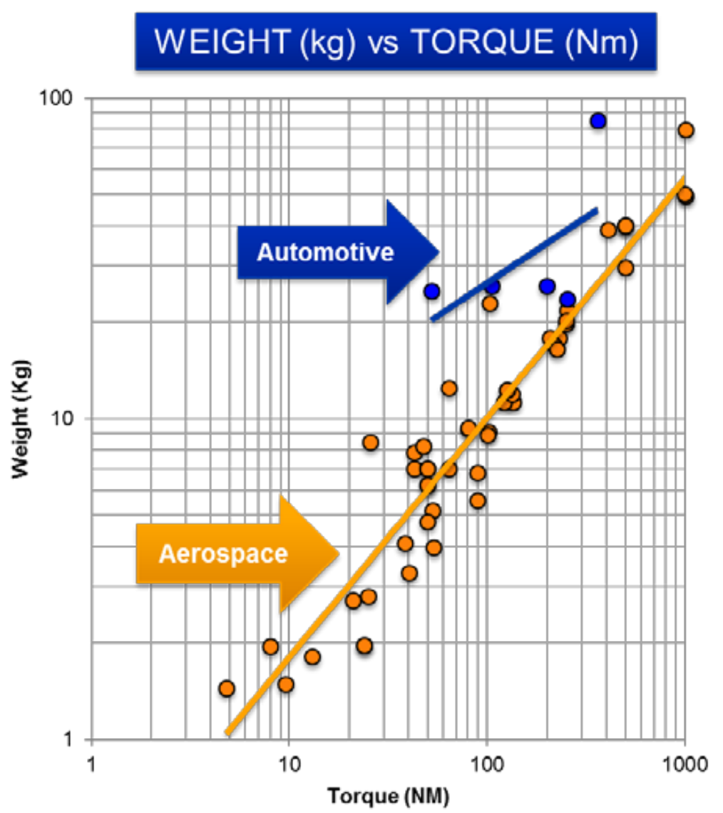
The relationship that ties maximum torque to weight is based on work by Duffy et al..
Based on this image we can extrapolate an equation to describe mass as a function of maximum torque:
$\(\text{motor\_mass} = 0.3151 \times \text{max\_torque}^{0.748}\)$
This motor mass relationship is based on continuous torque rating for aerospace motors.
This image is from the Duffy et al. research paper.
Motor Mission#
The motor mission takes as an input a scale factor, a motor map, a motor throttle (which can change during the mission), and an rpm. This component outputs torque, maximum torque, and the electrical power demand. All of these values are calculated for every point throughout the flight. The torque output can be sent to an attached propeller model. The maximum torque is used to determine maximum excess power, and when combined with a propeller model, enables the user to place constraints such as 300ft/min climb capability during cruise, which is typical to ensure FAR requirements for excess power in cruise are met. The electrical power demanded by the motor is determined based on the calculated efficiency of the motor at a given torque / RPM combination.
Motor Map#
The MotorMap() component takes in 0-1 values for electric motor throttle and scales those values into 0-max_torque on the motor map.
When paired with an RPM input value, this allows Aviary to solve for the motor efficiency.
The map itself is constructed using a structured meta model.
A structured meta model function is a smooth interpolation component for data that exists on a regular, structured, grid.
The original maps were put together for a 746kw (1,000 hp) electric motor published by Aretskin-Hariton et al.
An electric motor map is required to be supplied in Aviary options for the electric motor model to run successfully.
To do this, the user needs to set the Aviary option: Aircraft.Engine.Motor.DATA_FILE.
There is no default map.
An example map is contained in electric_motor_1800Nm_6000rpm.csv.
This map is sent both to motor_premission and motor_mission via the motor builder.
Unstructured Motor Maps#
If you have an unstructured motor map, i.e. a map that is similar to the above map but is missing the top right quadrant, the easiest way to handle that map is to just select torque data from the RPM that you will be running and input that subsection of the motor map as your motor map’s data. While this won’t allow for easily changing the RPM, it will result in properly scaled torque values for maps where maximum torque does vary by RPM.
Alternatively you could regularize the map.
That would involve adding in data for the missing sections and re-interpolating it onto a structured grid.
We recommend putting in very small efficiency values of 1 - 5 % to ensure that the optimizer does not create a final mission simulation that uses that part of the map.
If you don’t want to regularize the map, you could change the model in the builder from a MetaModelStructuredComp to a MetaModelUnStructuredComp.
However, doing this will cause issues with the maximum torque calculations.
If your max torque actually changes as a function of RPM, the current model cannot handle that.
In the basic model, maximum torque is calculated by looking at all the torque values all over the motor map and taking the maximum.
This max torque is then used to scale the throttle, which is always on a 0-1 scale.
If you are operating in an RPM regime where the max torque the motor can produce is less than the maximum torque of the motor overall, the resulting throttle values will be much smaller than you are expecting.
This is because you will effectively hit the max torque for your RPM before throttle goes all the way to 1.
In the worst case, you can always build your own electric motor external subsystem. This will allow you much finer control and insight into the inner workings of the electric motor, its power usage and mass scaling.
Electrical Power Consumption#
An assessment of how much electric power the motor consumes during normal operations can be accessed by looking at Dynamic.Vehicle.Propulsion.ELECTRIC_POWER_IN.
That will produce a vector of electric power usage during different parts of the mission.
This can serve as a starting point for how to size the electrical system.
However, the maximum possible electrical power required by the motor during exceptional conditions and off-nominal operations is not calculated by Aviary automatically.
The maximum electric power and maximum torque the motor would consume while ensuring 300ft/min climb capability in cruise, is not necessarily achieved at maximum throttle.
While this is usually the case in systems trying to shed mass, it is possible that it would be desirable to oversize the electric motor in order to run it at a more efficient part of the motor map.
This in turn may support 300ft/min climb compliance without requiring the motor to be run at maximum torque.
In those cases, the user would need to calculate for themselves what the maximum required torque was (not the maximum torque the motor was capable of producing which is already given by Aircraft.Engine.Motor.TORQUE_MAX).
The maximum torque would need to be calculated at every point in the flight regime, and then, based on the RPM and resulting efficiencies, this would need to be translated into a maximum electric power.
This could then allow for electrical system sizing.
Example Usage#
An example propulsion system with an electric motor coupled with a propeller can be reviewed in test_turboprop_model.py.
The key thing to remember when using the MotorBuilder() is to make sure you have set the motor map location by setting Aircraft.Engine.Motor.DATA_FILE in Aviary Options.
from aviary.subsystems.propulsion.test import test_turboprop_model
from aviary.utils.aviary_values import AviaryValues
from aviary.subsystems.propulsion.motor.motor_builder import MotorBuilder
import aviary.api as av

filename = 'electric_motor_1800Nm_6000rpm.csv'
options = AviaryValues()
options.set_val(av.Aircraft.Engine.Motor.DATA_FILE, av.get_path(filename))